NORMA
NORMA - Neutron Optics and Radiography for Material Analysis
Beamline responsible: Zoltán Kis, László Szentmiklósi
Contact: norma@bnc.hu
The NORMA facility is located at the end position of the neutron guide No 10/1 as a complementary part of the NIPS facility. It has been designed for neutron radiography (NR) and tomography (NT), and as position feedback for imaging-driven Prompt Gamma Activation Imaging (PGAI). In this latter mode, the combination with the element information obtained with the NIPS gamma spectroscopy detector makes it possible to assign element analysis results to a well-defined volume of a large object.

Figure 1. Operation modes of the NIPS-NORMA station
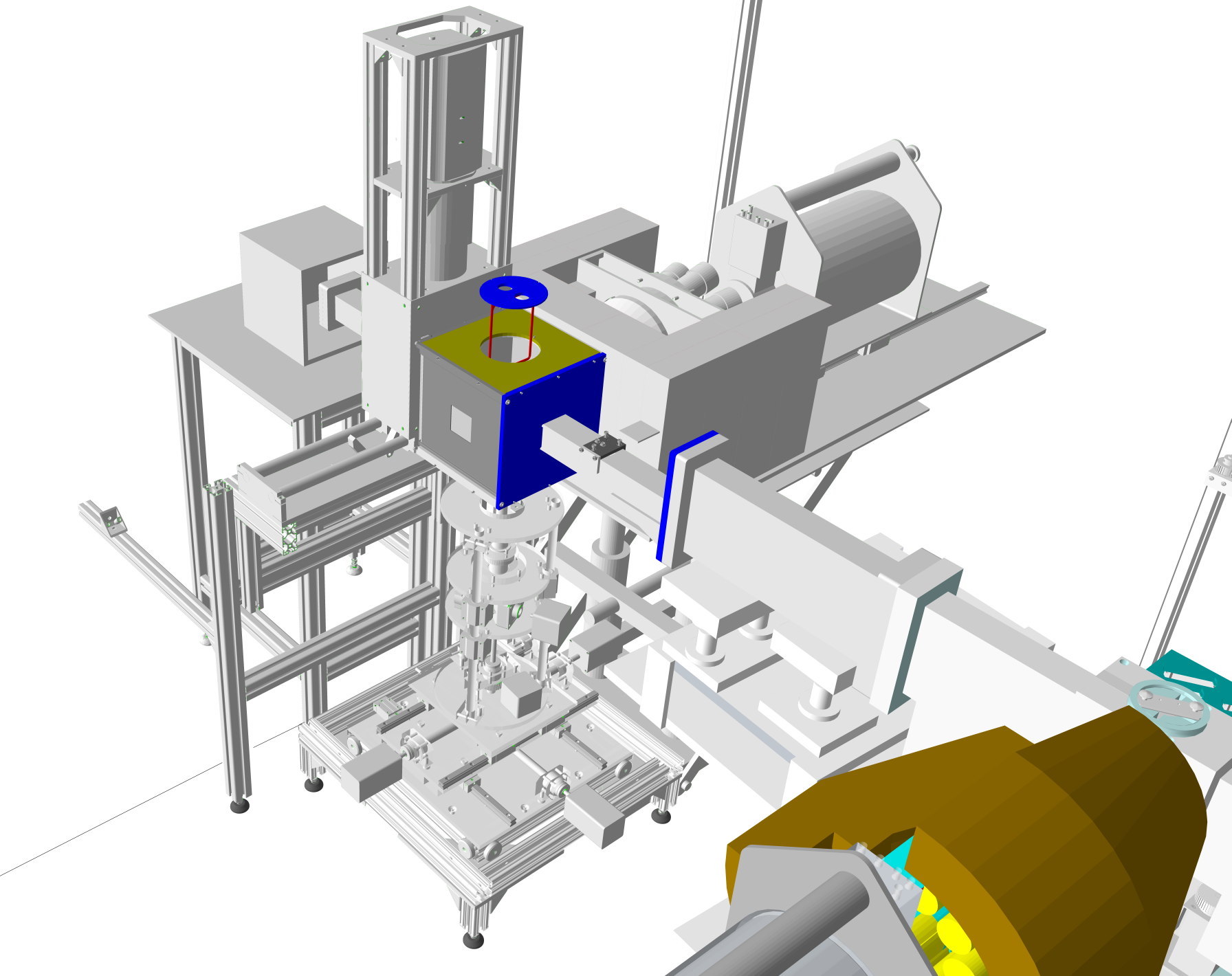
The beam arrives through a flight tube of 45×45 mm2 cross-section into a sample chamber with dimensions of 200×200×200 mm3 for imaging and position-sensitive applications. The frame of the chamber is made of AlMgSi alloy and lined from inside with 6Li-enriched polymer. By removing one or more side panels, larger objects (or at least parts of those) of up to 5 kg weight could also be imaged (such as a sword, vase, stone, etc.). Samples can be loaded manually from the top, or placed onto an XYZω motorized sample stage with a travel distance of 200 mm and a guaranteed precision of 15 μm. The sample stage is introduced to the sample chamber from the bottom.
The imaging system of the NORMA setup consists of a 100 μm thick 6Li/ZnS scintillator, an Al coated quartz mirror, and a cooled, black-and-white, back-illuminated Andor iKon-M CCD camera with 1024×1024 pixels and 16-bit pixel depth, mounted in a light-tight aluminum housing. The custom optics projects a 48.6×48.6 mm2 field of view (in which the beam spot is about 40×40 mm2) onto the 13.3×13.3 mm2 sensitive surface of the CCD chip.
The spatial resolution of the imaging system varies between 230‑660 μm. A motorized pinhole exchanger and a graphite scatterer (SuperNORMA) are installed at the end of the neutron guide, which is capable of adjusting the L/D ratio, a measure of the neutron beam’s divergence, and at the same time making the beam spot more homogeneous. The pinhole system is fabricated from a Li-6 enriched poly sheet with a neutron attenuation factor of at least 1000. It has three positions with aperture sizes of 550 mm2 (25×22 mm2, the original), 121.54 mm2 (Ø12.44 mm), 9.95 mm2 (Ø3.54 mm). There are two graphite scatterers with 2 mm and 3 mm thicknesses placed upstream, which could be positioned independently of the pinholes. The L/D ratio of the beam is now adjustable between 233 (550 mm2), 500 (121.54 mm2), and 1832 (9.95 mm2). It means that the distance from the screen where the spatial resolution is mostly affected only by the inherent resolution of the scintillation screen (about 200 µm) could be extended from 20 mm to about 100 mm, as demonstrated in Figure 2. The advantage of the extended range of better spatial resolution plays an important role in the tomography of larger objects. The more uniformly irradiated field of view helps in normalizing the images properly, at the price of somewhat longer exposure times.

Figure 2. The spatial resolution of NORMA as a function of screen-to-object distance. Note that higher L/D ratio results in more even spatial resolution, but longer exposure times.
The spatial distribution of the beam intensity, as well as the energy distribution of the neutrons, measured by the time-of-flight technique, are illustrated in Fig. 3.

Figure 3. (left) the wavelength and the energy-dependence of the neutron beam. (right) The neutron beam intensity at the sample position of the NIPS/NORMA facility, with and without the graphite scatterer inserted at the end of the neutron guide.
The specifications of the facility are listed in Table 1.
|
Beam size for imaging: |
up to 40×40 mm2 |
|
Beam cross-section for PGAA/PGAI: |
continuously adjustable rectangular slit |
|
Collimation ratio (L/D) : |
233 – 1832 |
|
Beam energy distribution: |
Cold beam |
|
Thermal-equivalent flux at target: |
2.7×10⁷n cm-2s-1 |
|
Scintillator screen : |
100 µm thick 6Li/ZnS scintillator on an Al plate |
|
Mirror: |
Al coated quartz mirror set in 45º to the neutron beam |
|
Lens: |
Canon EF 85mm f1.2 L II USM |
|
Standard imaging detector : |
Back-illuminated Andor iKon-M 934 CCD camera with 1024×1024 pixels and 16-bit pixel depth |
|
Spatial resolution: |
230‑660 μm according to the 1.5‑100.5 mm distance from the scintillator screen |
|
Sample stage: |
xyzω motorized sample stage with a travel distance of 200 mm and a guaranteed precision of 15 μm |
|
Sample chamber dimensions: |
200×200×200 mm3 |
|
Sample environment: |
Ambient pressure and temperature |
Table 1. Specifications of the NORMA facility
The radiograms taken at NORMA require several steps of data treatment. The spatial inhomogeneity of the beam and the thermal noise of the camera should be removed. These are called ‘beam image or flat-field correction’ and ‘dark current correction’, respectively. In tomography, the goal is to determine a measure of the interaction probability between the material and the neutron as a function of spatial coordinates. This quantity delivers structural information about the interior of the sample. The reconstruction codes, such as the OCTOPUS reconstruction software, apply the inverse Radon-transformation and filtered back projection algorithms. The visualization of the dataset in 3D space (volume rendering) is carried out using VGStudio MAX 3.2.

Figure 4. The 3D view of the NORMA imaging station
Reference:
Z. Kis, L. Szentmiklósi, T. Belgya: NIPS–NORMA station - A combined facility for neutron-based nondestructive element analysis and imaging at the Budapest Neutron Centre Nucl. Instr. Meth. A 779 (2015)116–123 DOI: 10.1016/j.nima.2015.01.047
Szentmiklósi László, Kis Zoltán, Belgya Tamás, Maróti Boglárka, Horváth László Zoltán, Papp Mariann: Roncsolásmentes képalkotás neutronokkal és röntgensugárzással a Budapesti Neutron Centrumban, Fizikai Szemle 67/7-8 (2017) 240-244.
